
 I led three workshops with three participants, two workshops with two people, and two workshops with just one participant. Fifteen people participated. Each workshop followed the format described below, with the exception of the first two sessions. These initial workshops were over one hour and featured potentiometers, servos, and Piezo buzzers. After observing user fatigue during these workshops, I edited both the booklet and kit components to focus only on the LED output and moisture sensor input.
Workshop Procedure
- Welcome the participants, review consent forms, hand out a pre-study survey.
- Using the booklet as a guide, begin a conversation about using microcontrollers, encouraging questions along the way. Main points include: How is a microcontroller like a desktop computer or laptop? What do we mean by inputs and outputs? How are Makers currently using microcontrollers?
- Identify materials in the kit.
- Beginning with the simplest circuit possible, ask the participants to turn on the LED attached to a copper tape circuit by connecting the battery. Have the participants use other conductive materials to demonstrate how conductive thread or 22 gauge wire or snaps can form circuits.
- Discuss making a similar circuit with the Gemma, an LED and a battery pack. [The Gemmas are programmed to turn on an LED on pin 0, so that when the circuit is correctly wired, the light will go on.] Using a large visual aid, identify color-coded pins on the Gemma.
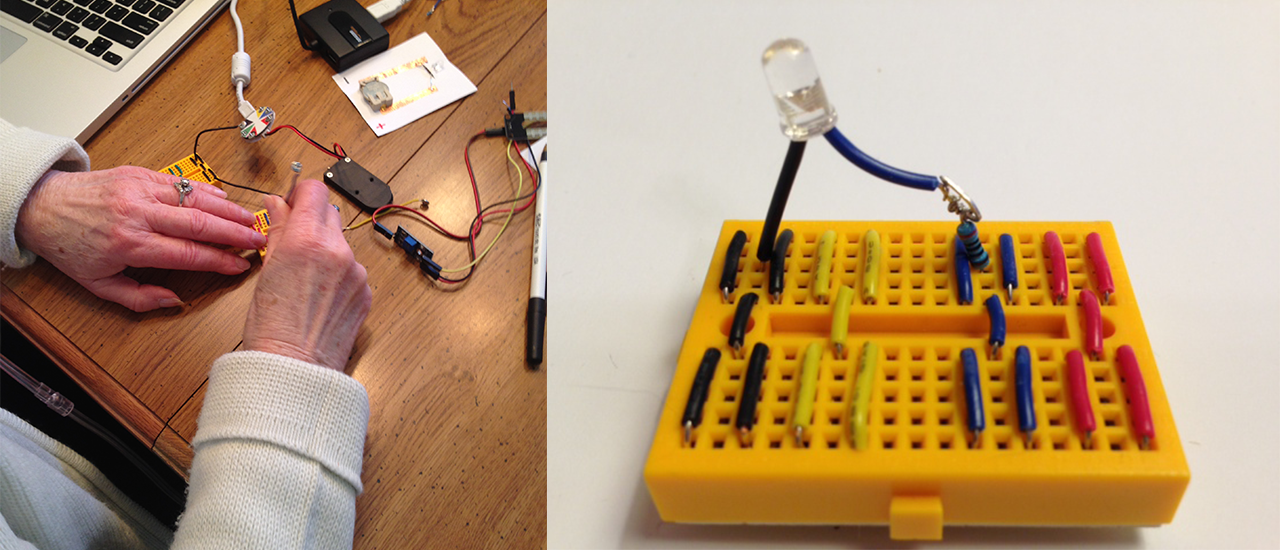
- Walk participants through the structure of the bread- board. Participants wire their own circuits.
- Introduce the Arduino software. Using a poster featuring the code from the Blink sketch, step through each line of code and explain basic Arduino syntax.
- Outline the process of uploading the sketch to the Gemma by pressing the small reset button on the board, followed by clicking the upload button within a few seconds. LEDs should light for one second and turn off for one second.
- Discuss the variables in the code and have participants make their own changes in the Arduino environment, changing the rate of blinking.
- 10.Leaving the LED in place as an output, introduce the hygrometer as an input device. Returning to the Gemma diagram, point out the yellow input pin and the two red power pins as new additions to the wiring. Participants should be able to complete the circuit for the hygrometer in the same way they wired the LED, with minimal guidance.
- With the Soil Moisture sketch open in the Arduino environment, ask the users to upload the sketch as they had done previously. Due to the far more com- plex nature of this sketch, do not go through it line by line, but instead focus on the familiar part of the sketch that turns on the LED when the sensor is moist. Ask the participants how to make the hygrometer more effective by changing the sketch slightly. The users should change the code so that the LED lights up when the sensor is dry, indicating that the plant needs to be watered. Use a moist paper towel to test the sensor, or a small potted plant. Ask participants to come up with other extensions for this sensor.
- Ask for questions and feedback. Distribute the post- study surveys. Lead group discussion reflecting on the experience.